







Executive Overview
As high-density computing loads and artificial intelligence workloads push data center power densities to unprecedented levels, the thermal management systems underpinning these facilities face intense scrutiny. Continuous electrical-to-thermal conversion means that data center cooling infrastructure must operate without interruption. To protect against thermal failure, facility designers routinely implement resilient architectures on paper, incorporating redundant components such as Computer Room Air Handlers (CRAHs), Coolant Distribution Units (CDUs), secondary pumps, and multi-sourced power feeds.
However, a dangerous disconnect exists between mechanical redundancy and operational independence. While a schematic may show an $N+1$ configuration—implying robust protection against single-point failures—these disparate physical assets frequently rely on a centralized digital nervous system. A shared supervisory controller, a single network switch, a common control power supply, or a localized sensor can form a single point of failure (SPOF). When this shared layer collapses, it can instantly translate a localized anomaly into a catastrophic, facility-wide failure domain.
This investigative report examines the hidden vulnerabilities inside modern data center cooling topologies. By analyzing the structural flaws of centralized optimization, the compounding risks introduced by advanced liquid cooling architectures, and the imperative for autonomous local fallback systems, industry stakeholders can begin to bridge the gap between design intent and real-world resilience.
Detailed Chronology of an Invisible Failure
To understand how a multi-million-dollar cooling plant can be brought to its knees by a minor digital glitch, it is helpful to trace the cascading chain of events typical of a control-layer failure. This hypothetical yet representative chronology illustrates how mechanical redundancy is routinely bypassed by software and communication dependencies.
T-Minus 00:00:15 — The Steady State
A enterprise-scale data center operates at a high utilization rate, drawing megawatts of power across thousands of AI accelerators. The thermal plant runs a standard $3+1$ pump configuration. Three pumps operate continuously to maintain design flow, while a fourth stands ready on hot standby. Supervisory control is managed by a centralized Plant Management System (PMS), which continuously polls variable-speed drives, optimizes pressure setpoints, and stages lead-lag operations across the chiller plant.
T-Minus 00:00:02 — The Transient Anomaly
A minor firmware glitch or a localized micro-surge affects the primary industrial network switch governing the supervisory control bus. Mechanically, the pumps are pristine. Electrically, their motors are energized and connected to stable busbars. However, the continuous polling loop managed by the central supervisory controller experiences a momentary freeze.
T-Minutes 00:00:00 — The Supervisory Collapse
The central plant controller locks up. In a poorly designed topology, the software architecture treats the supervisory link as an absolute prerequisite for operation. Without a continuous "heartbeat" signal from the central PMS, the local programmable logic controllers (PLCs) embedded in the pump skids default to a safety lockout state, misinterpreting the loss of communication as a critical system-wide fault rather than a localized network interruption.
T-Plus 00:00:05 — The Cascading Thermal Spike
Because the supervisory layer has dropped out, the running duty pumps halt their cycles. The standby pump, despite being mechanically sound and fully fueled by redundant power paths, refuses to start because its command logic relies on the incapacitated master controller. Water flow drops to zero. Within seconds, the thermal mass of the servers begins to absorb unmitigated heat energy. Coolant temperatures spike inside the direct-to-chip loops, forcing thermal throttling across mission-critical compute nodes.
T-Plus 00:02:00 — Emergency Mitigation
Facility engineers, alerted by a flood of high-priority alarms, manually override the system, switching local panels to manual control modes to restart the pumps. While catastrophe is averted through human intervention, the incident highlights a harsh reality: the facility had two of everything mechanically, but only one path to a critical operational decision.
Supporting Context & Metrics: The Anatomy of Failure Domains
A failure domain is strictly defined as the exact physical or logical boundary of a system that can be compromised by a single fault. In traditional mechanical engineering, calculating a failure domain is relatively straightforward: if a pipe bursts or a motor seizes, the isolation valves close, and the surrounding redundancy absorbs the load.
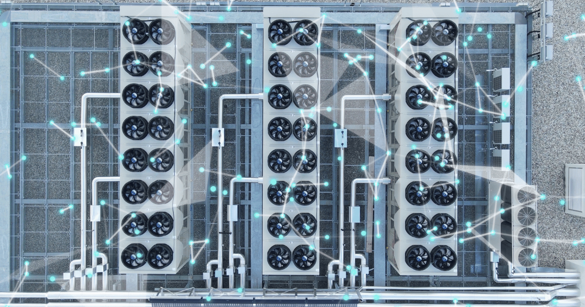
In modern digital-mechanical hybrids, however, failure domains are multidimensional. They encompass fluid dynamics, electrical distribution, and digital control networks.
+-------------------------------------------------------------+
               TRADITIONAL N+1 MECHANICAL SCHEDULING
+-------------------------------------------------------------+
   [ Pump A (Duty) ]    [ Pump B (Duty) ]    [ Pump C (Duty) ]
                               |                    /
                               |                   /
             +------------------+------------------+
                                |
                        [ Pump D (Standby) ]
*(Appears robust on paper; masks underlying digital dependencies)*
The Illusion of Mechanical Redundancy
Consider a standard pump skid comprising four identical units: three duty pumps and one standby pump. On a mechanical schematic, this configuration satisfies classic $N+1$ criteria. If a bearing seizes on Pump A, the motor trips, Pump A drops out of service, and the standby pump (Pump D) automatically energizes to maintain required flow rates.
The domain of failure for that mechanical event is exactly one unit.
However, if all four pumps receive their start commands, lead-lag selection algorithms, and speed staging signals from a single supervisory controller—without a local fallback program—the operational reality shifts dramatically. A fault within that single controller strips the system of its operational independence. The machines remain mechanically redundant, but they are operationally unified.
The Proliferation of Liquid Cooling Layers
This vulnerability is accelerating rapidly with the industry-wide transition toward direct-to-chip liquid cooling and rear-door heat exchangers (RDHx). To manage complex fluid dynamics, modern cooling plants incorporate an array of new devices:
- Coolant Distribution Units (CDUs)
- Variable-Speed Pumps (VFDs)
- Automated Control Valves
- Precision Differential Pressure Sensors
- Distributed Leak Detection Loops
Each of these components adds a new layer of control, communication cabling, and firmware logic. Consequently, a cooling plant can fail entirely due to a software timeout or a severed communication bus—dependencies that never appear on standard piping and instrumentation diagrams (P&IDs).
Expert Perspectives & Industry Analysis
Control and automation engineers emphasize that the industry must evolve past antiquated definitions of resilience that focus solely on hardware counts.
"A system can have two of everything and still have only one path to a critical decision," notes Fatih Gündoğan, an industrial automation and control engineer. "If that singular path has never been deliberately severed during commissioning, the resilience depicted on the engineering drawings has never been proven in actual operation."
According to industry analysts, the historic separation between facilities teams (Mechanical/Electrical) and IT/Automation teams (Software/Controls) has contributed significantly to this blind spot. While facility engineers rigorously test backup generators and UPS battery strings, the control loops governing the thermal plant are frequently trusted implicitly once the software passes factory acceptance testing.
Furthermore, centralized optimization systems—designed explicitly to maximize Power Usage Effectiveness (PUE) and Water Usage Effectiveness (WUE)—often overstep their bounds. While plant-level logic is necessary to optimize pressure setpoints and coordinate chillers, it must never become an absolute bottleneck for basic fluid circulation. When optimization logic becomes a single point of failure, the pursuit of maximum efficiency actively undermines foundational reliability.

Designing for Degraded Operation: A Strategic Framework
Mitigating control-layer vulnerabilities does not require doubling every PLC, sensor, and network cable in the facility—an approach that would introduce prohibitive capital costs and unmanageable system complexity. Instead, engineers must adopt a philosophy of graceful degradation and autonomy by design.
1. Local Autonomy for Critical Loops
Local controllers, such as PLCs embedded directly within pump panels or unit-level controllers on CRAHs, must retain sufficient computational autonomy to maintain basic operations when higher-level supervisory networks fail.
If upstream communication with the Building Management System (BMS) or Plant Management System is lost, local controllers should be programmed to:
- Hold their last known safe pressure setpoint or flow rate.
- Revert to a predefined, safe middle-range pump speed.
- Fall back to locally wired temperature or pressure sensors rather than relying exclusively on remote digital telemetry.
- Permit immediate, intuitive manual control at the local panel interface.
2. Redefining Commissioning Protocols
Standard functional testing must expand beyond verifying that a spare mechanical unit starts when its primary counterpart fails. Commissioning teams must intentionally test the failure domain of the control layer itself.
Rigorous test scripts should incorporate active disruption of the supervisory layer:
- Network Disconnection: Physically severing the supervisory Ethernet ring while the plant operates at peak thermal load to verify that local controllers maintain fluid circulation.
- Controller Power Cycle: Intentionally rebooting the primary plant controller to observe whether downstream equipment drops out or safely defaults to autonomous local control.
- Sensor Signal Corruption: Simulating the loss or invalidation of remote differential-pressure signals to ensure seamless fallback to local backup instrumentation.
Future Outlook: The Next Generation of Resilient Thermal Infrastructure
As artificial intelligence workloads densify cabinets beyond 100 kW per rack, the margin for thermal error shrinks to near zero. Traditional air-cooled architectures are rapidly giving way to closed-loop liquid systems where a momentary loss of coolant flow can trigger catastrophic silicon degradation in a matter of seconds.
In response, data center operators are beginning to mandate stricter control-layer architectures:
- Decentralized Edge Intelligence: Moving away from monolithic, centralized control rooms toward edge-computed, highly distributed resilient nodes where individual cooling units make autonomous safety decisions.
- Deterministic Industrial Networks: Replacing standard enterprise IT networking protocols within the thermal plant with deterministic, highly fault-tolerant industrial fieldbuses equipped with hardware-level redundancy.
- Continuous Chaos Engineering for Facilities: Adopting software-inspired chaos engineering principles—routinely injecting faults into the cooling plant’s control and communication layers during scheduled maintenance windows to verify real-world survivability.
Ultimately, true data center resilience requires looking past the comforting symmetry of equipment schedules. An $N+1$ design is only as robust as its weakest dependency. By auditing shared control layers, engineering for degraded autonomy, and stress-testing the digital infrastructure as rigorously as the physical hardware, the data center industry can build cooling plants capable of surviving not just mechanical breakdowns, but the complex software dependencies that govern them.